Monday 23 May 2016

The Steady Flow Energy Equation (SFEE)

The Steady Flow Energy Equation (SFEE) is used for open systems to determine the total energy flows.
It is assumed that the mass flow through the system is constant.
It is also assumed that the total energy input to the system is equal to the total energy output.
The energies that are included are;
          internal, flow, kinetic, potential, heat and work.
The equation is shown below where suffix 1 is the entrance and suffix 2 the exit from the system.


where:
u          =          internal energy (J)
P          =          pressure (N/m2)
v          =          volume (m3)
C          =          velocity (m/s)
g          =          acceleration due to gravity (m/s2)
Z          =          height above a datum (m)
Q         =          heat flow (J)
W         =          work (J)

The term P .v  represents the displacement or flow energy.
The term  C/ 2   represents the kinetic energy.
The term g. Z  represents the potential energy.

 
In thermodynamics the changes in potential energy are usually small except for example a water reservoir supplying water to a low level turbine.
In the following examples we can omit the potential energy term thus simplifying the equation to;


u1  +  P1v1  +           +  Q   =    u2  +  P2v2  +            +  W


Also the term  ( u  +   P.v ) is also known as specific enthalpy (h), so the equation is now written;


h1  +            +  Q   =    h2  +            +  W


Example 1

In a steady flow open system a fluid flows at a rate of 4 kg/s.
It enters the system at a pressure of 6 bar, a velocity of 220 m/s, internal energy
2200 kJ/kg and specific volume 0.42 m3/kg.
It leaves the system at a pressure of 1.5 bar, a velocity of 145 m/s, internal energy
1650 kJ/kg and specific volume 1.5 m3/kg.
During its passage through the system, the fluid has a loss by heat transfer of 40kJ/kg to the surroundings.
Determine the power of the system, stating whether it is from or to the system.
Neglect any change in potential energy.


u1  +  P1v1  +                +    Q   =       u2  +  P2v2  +               +   W


Power from the system (kW)   = Work output (kJ/kg) x mass flow rate of fluid (kg/s)

Work output (kJ/kg) can be found by rearranging the SFEE.

We can work in kilojoules (kJ). This means that the  kinetic energy section of the SFEE will be divided by 103 to put it in kJ.


W  =   ( u1  -  u2)   +  ( P1v1  -    P2v2 ) +   (                 )  +  Q


2 x 10³
 
W   =   ( 2200  -  1650 )  +  ( 600  x  0.42    -   150  x  1.5 )  +  (                     )   – 40

W  =    550     +      27         +         13.69          -    40

W   =    550.69  kJ/kg

This is positive so it is energy output from the system.

Power from the system (kW)   =           W    x  m
                                   
                                                =          550.69   x   4 kg/s

                                                =          2202.76 kW

Newton's Three Laws of Motion

Newton's First Law of Motion:

I. Every object in a state of uniform motion tends to remain in that state of motion unless an external force is applied to it.
This we recognize as essentially Galileo's concept of inertia, and this is often termed simply the "Law of Inertia".

Newton's Second Law of Motion:

II. The relationship between an object's mass m, its acceleration a, and the applied force F is F = ma. Acceleration and force are vectors (as indicated by their symbols being displayed in slant bold font); in this law the direction of the force vector is the same as the direction of the acceleration vector.
This is the most powerful of Newton's three Laws, because it allows quantitative calculations of dynamics: how do velocities change when forces are applied. Notice the fundamental difference between Newton's 2nd Law and the dynamics of Aristotle: according to Newton, a force causes only a change in velocity (an acceleration); it does not maintain the velocity as Aristotle held.
This is sometimes summarized by saying that under Newton, F = ma, but under Aristotle F = mv, where v is the velocity. Thus, according to Aristotle there is only a velocity if there is a force, but according to Newton an object with a certain velocity maintains that velocity unless a force acts on it to cause an acceleration (that is, a change in the velocity). As we have noted earlier in conjunction with the discussion of Galileo, Aristotle's view seems to be more in accord with common sense, but that is because of a failure to appreciate the role played by frictional forces. Once account is taken of all forces acting in a given situation it is the dynamics of Galileo and Newton, not of Aristotle, that are found to be in accord with the observations.

Newton's Third Law of Motion:


III. For every action there is an equal and opposite reaction.

Archimedes' Principle or Law

Archimedes' Principle or Law


archimedes buoyant force
Archimedes' principle states that:
"If a solid body floats or is submerged in a liquid - the liquid exerts an upward thrust force - buoyant force - on the body equal to the gravitational force on the liquid displaced by the body."
The buoyant force can be expressed as
F=  W
    = V γ
    = V ρ g     (1)
where
FB = buoyant force acting on the submerged or floating body (N, lbf)
W = weight of the displaced liquid (N, lbf)
V = volume of the body below the surface of the liquid (m3, ft3)
γ   = specific weight of the fluid (weight per unit volume) (N/m3, lbf/ft3)
ρ = density of the fluid (kg/m3, slugs/ft3)
g = acceleration of gravity (9.81 m/s2, 32.174 ft/s2

Example - Density of a Body that floats in Water

A body that floats is 96% submerged in water with density 1000 kg/m3.
For a floating body the buoyant force equal the weight of the displaced water.
F=  W
or
Vb ρb g = Vw ρw g 
where
Vb = volume body (m3)
ρb = density body (kg/m3)
V= volume water (m3)
ρw  = density water (kg/m3)
The equation can be transformed to
ρb Vw ρw / Vb 
Since 95% of the body is submerged
0.95 Vb = Vw 
and the density of the body can be calculated as
ρb = 0.95 Vb (1000 kg/m3) / Vb
    = 950 kg/m3

Example - Buoyant force acting on a Brick submerged in Water

A standard brick with actual size 3 5/8 x 2 1/4 x 8 (inches) is submerged in water with density 1.940 slugs/ft3. The volume of the brick can be calculated as
Vbrick = (3 5/8 in) (2 1/4 in) (8 in)
         = 65.25 in3
The buoyant force acting on the brick is equal to the weight of the water displaced by the brick and can be calculated as
F=  ((65.25 in3) / (1728 in/ft3)) (1.940 slugs/ft3) (32.174 ft/s2)  
    = 2.36 lbf
The weight or the gravity force acting on the brick - common red brick has specific gravity 1.75 - can be calculated to
WB = (2.36 lbf) 1.75
     = 4.12 lbf
The resulting force acting on the brick can be calculated as
W(WB - FB) = (4.12 lbf) - (2.36 lbf)
   = 1.76 lbf

Calorific values

Calorific values

The calorific value of a fuel is the quantity of heat produced by its combustion - at constant pressure and under "normal" ("standard") conditions (i.e. to 0oC and under a pressure of 1,013 mbar).

The combustion process generates water vapor and certain techniques may be used to recover the quantity of heat contained in this water vapor by condensing it.
  • Higher Calorific Value (or Gross Calorific Value - GCV, or Higher Heating Value - HHV) -  the water of combustion is entirely condensed and that the heat contained in the water vapor is recovered
  • Lower Calorific Value (or Net Calorific Value - NCV, or Lower Heating Value - LHV) - the products of combustion contains the water vapor and that the heat in the water vapor is not recovered
FuelHigher Calorific Value
(Gross Calorific Value - GCV)
Lower Calorific Value
(Net Calorific Value - NCV)
kJ/kgBtu/lbkJ/kg
Acetone29000
Alcohol 96%30000
Anthracite32500 - 3400014000 - 14500
Bituminous coal17000 - 232507300 - 10000
Butane495102090045750
Carbon34080
Charcoal2960012800
Coal (Lignite - Anthrasite)15000 - 270008000 - 14000
Coke28000 - 3100012000 - 13500
Diesel fuel448001930043400
Ethane5190047800
Ethanol2970012800
Ether43000
Gasoline473002040044400
Glycerin19000
Hydrogen14179061000121000
Kerosene4620043000
Lignite163007000
Methane55530 50000
Methanol23000
Oil, heavy fuel43000
Oil, light distillate48000
Oil, light fuel44000
Oils vegetable39000 - 48000
Paraffin4600041500
Peat13800 - 205005500 - 8800
Pentane45350
Petrol48000
Petroleum43000
Propane50350 46350
Semi anthracite26700 - 3250011500 - 14000
Sulfur9200
Tar36000
Turpentine44000
Wood (dry)14400 - 174006200 - 7500
kJ/m3Btu/ft3
Acetylene56000
Butane C4H101330003200
Hydrogen13000
Natural gas43000950 - 1150
Methane CH439820 
Propane C3H81010002550
Town gas18000
kJ/lBtu/Imp gal
Gas oil38000164000
Heavy fuel oil41200177000
Kerosene35000154000
  • 1 kJ/kg = 1 J/g = 0.4299 Btu/ lbm = 0.23884 kcal/kg
  • 1 Btu/lbm = 2.326 kJ/kg = 0.55 kcal/kg
  • 1 kcal/kg = 4.1868 kJ/kg = 1.8 Btu/lbm
  • 1 dm3 (Liter) = 10-3 m3 = 0.03532 ft3 = 1.308x10⁻³ yd3 = 0.220 Imp gal (UK) = 0.2642 Gallons (US)

Scavenging Methods

Since one engine cycle in a two-stroke engine is completed in one crankshaft rotation, gas exchange has to occur while the piston is near BDC. There are two important consequences of this:
  1. Since gas exchange commences before and ends after BDC, a portion of the expansion and compression stroke is unusable.
  2. Piston velocity is low during the entire gas exchange phase and is unable to provide a significant pumping effect on the cylinder charge. Hence, gas exchange can only occur when the intake pressure is sufficiently higher than the exhaust pressure to allow the incoming fresh charge to displace the burned gas in the time available. This process of simultaneously purging exhaust gas from the previous cycle and filling the cylinder with fresh charge for a new cycle is referred to as scavenging. To ensure adequate scavenging, two-stroke engines must be equipped with some form of intake air compression and the intake and exhaust ports and/or valves must be open simultaneously for a sufficient period of time.
Both valves in the cylinder head and ports in the cylinder liner are applied as gas exchange control elements. In the case of ports, the piston also assumes the function of a control slide.
Scavenging in two-stroke engines is performed mainly by one of three methods:
  • Cross-scavenging
  • Loop-scavenging
  • Uniflow-scavenging

To Measure Indicated Power in Diesel Engine with Indicator Diagram

The burning of fuel in an engine cylinder (2 stroke or 4 stroke diesel engine) will result in the production of power at an output shaft, some of the power produced in the cylinder will be used to drive the rotating masses of the engine.
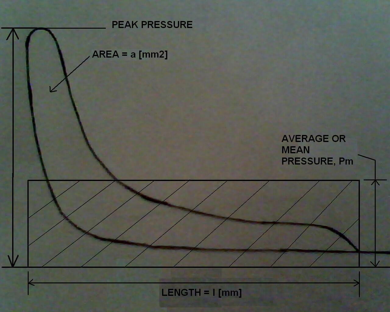
Typical indicator diagram for a 2 stroke engine is shown in figure below. This power card or pv diagram can be used to measure indicated power in diesel engines. The area within the diagram represents the work done within the cylinder in one cycle.
measuring indicated power of diesel engine
Measuring Indicated Power of Diesel Engine
The area can be measured by an instrument known as ‘Planimeter’ or by the use of the mid ordinates rule. [On modern engines this diagram can be continuously taken by employing two transducers, one pressure transducer in the combustion space and other transducer on the shaft. Through the computer we can thus get on line indicated diagram and power of all cylinders.]
The area is then divided by the length of the diagram in order to obtain mean height. This mean height, when multiplied by the spring scale of the indicator mechanism, gives the indicated mean effective pressures for the cylinder. The mean effective or average pressure [Pm] can now be used to determine the workdone in the cylinder. Following calculations can be made to the area of indicator diagram to measure indicated power.

Calculations

Area of the indicator diagram = a [mm2]
Average height of the diagram = a [mm2] / l [mm]
Average mean indicator pressure = a [mm2] / l [mm] x k [bar / mm]
or P= ( a / l ) x k [bar]
where k = spring scale in bar per mm

Work done in one cycle = Mean Indicated Pressure x Area of the Piston x Length of stroke
= [Pm] x [A] x [L]
To obtain the power of this unit, it is necessary to determine the rate at which work is done,
i.e. multiply work by number of power strokes in one second.

Now, Indicated Power of Unit [ip] =

Mean Indicated Pressure [Pm] x Area of Piston [A] x Length of Stroke [L] x Number of Power Strokes per Second [N]
or

Indicated Power of Unit = Pm L A N

Unit of Final Result

Indicated Power = Pm L A N
= ( a / l ) x k [bar] x L [m] x A [m2] x N [1/s]
= [bar] x [m] x [m2] x [1/s]
= 10N/m2 x m x m2 x 1/s
= 10Nm/s
= 10Joules/s
= 10Watts
Hence, multiply the result obtained from calculating indicated power with 105 and the final unit will be in Watts

Air Compressor

Air Compressor


It was common for shops to have a central power source that drove all the tools through a system of belts, wheels and driveshafts. The power was routed around the work space by mechanical means. While the belts and shafts may be gone, many shops still use a mechanical system to move power around the shop. It's based on the energy stored in air that's under pressure, and the heart of the system is the air compressor.
You'll find air compressors used in a wide range of situations—from corner gas stations to major manufacturing plants. And, more and more, air compressors are finding their way into home workshops, basements and garages. Models sized to handle every job, from inflating pool toys to powering tools such as nail guns, sanders, drills, impact wrenches, staplers and spray guns are now available through local home centers, tool dealers and mail-order catalogs.
The big advantage of air power is that each tool doesn't need its own bulky motor. Instead, a single motor on the compressor converts the electrical energy into kinetic energy. This makes for light, compact, easy-to-handle tools that run quietly and have fewer parts that wear out.
Air compressor types
While there are compressors that use rotating impellers to generate air pressure, positive-displacement compressors are more common and include the models used by homeowners, woodworkers, mechanics and contractors. Here, air pressure is increased by reducing the size of the space that contains the air. Most of the compressors you'll run across do this job with a reciprocating piston.
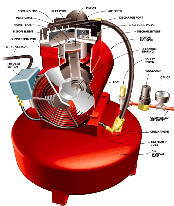
Like a small internal combustion engine, a conventional piston compressor has a crankshaft, a connecting rod and piston, a cylinder and a valve head. The crankshaft is driven by either an electric motor or a gas engine. While there are small models that are comprised of just the pump and motor, most compressors have an air tank to hold a quantity of air within a preset pressure range. The compressed air in the tank drives the air tools, and the motor cycles on and off to automatically maintain pressure in the tank.
At the top of the cylinder, you'll find a valve head that holds the inlet and discharge valves. Both are simply thin metal flaps–one mounted underneath and one mounted on top of the valve plate. As the piston moves down, a vacuum is created above it. This allows outside air at atmospheric pressure to push open the inlet valve and fill the area above the piston. As the piston moves up, the air above it compresses, holds the inlet valve shut and pushes the discharge valve open. The air moves from the discharge port to the tank. With each stroke, more air enters the tank and the pressure rises.
Typical compressors come in 1- or 2-cylinder versions to suit the requirements of the tools they power. On the homeowner/contractor level, most of the 2-cylinder models operate just like single-cylinder versions, except that there are two strokes per revolution instead of one. Some commercial 2-cylinder compressors are 2-stage compressors–one piston pumps air into a second cylinder that further increases pressure.
Compressors use a pressure switch to stop the motor when tank pressure reaches a preset limit–about 125 psi for many single-stage models. Most of the time, though, you don't need that much pressure. Therefore, the air line will include a regulator that you set to match the pressure requirements of the tool you're using. A gauge before the regulator monitors tank pressure and a gauge after the regulator monitors air-line pressure. In addition, the tank has a safety valve that opens if the pressure switch malfunctions. The pressure switch may also incorporate an unloader valve that reduces tank pressure when the compressor is turned off.
Many articulated-piston compressors are oil lubricated. That is, they have an oil bath that splash-lubricates the bearings and cylinder walls as the crank rotates. The pistons have rings that help keep the compressed air on top of the piston and keep the lubricating oil away from the air. Rings, though, are not completely effective, so some oil will enter the compressed air in aerosol form.
Having oil in the air isn't necessarily a problem. Many air tools require oiling, and inline oilers are often added to increase a uniform supply to the tool. On the down side, these models require regular oil checks, periodic oil changes and they must be operated on a level surface. Most of all, there are some tools and situations that require oilfree air. Spray painting with oil in the airstream will cause finish problems. And many new woodworking air tools such as nailers and sanders are designed to be oilfree so there's no chance of fouling wood surfaces with oil. While solutions to the airborne oil problem include using an oil separator or filter in the air line, a better idea is to use an oilfree compressor that uses permanently lubricated bearings in place of the oil bath.
A variation on the automotive-type piston compressor is a model that uses a one-piece piston/connecting rod. Because there is no wrist pin, the piston leans from side to side as the eccentric journal on the shaft moves it up and down. A seal around the piston maintains contact with the cylinder walls and prevents air leakage.
Where air requirements are modest, a diaphragm compressor can be effective. In this design, a membrane between the piston and the compression chamber seals off the air and prevents leakage.
Compressor power
One of the factors used to designate compressor power is motor horsepower. However, this isn't the best indicator. You really need to know the amount of air the compressor can deliver at a specific pressure.
The rate at which a compressor can deliver a volume of air is noted in cubic feet per minute (cfm). Because atmospheric pressure plays a role in how fast air moves into the cylinder, cfm will vary with atmospheric pressure. It also varies with the temperature and humidity of the air. To set an even playing field, makers calculate standard cubic feet per minute (scfm) as cfm at sea level with 68 degrees F air at 36% relative humidity. Scfm ratings are given at a specific pressure–3.0 scfm at 90 psi, for example. If you reduce pressure, scfm goes up, and vice versa.
You also may run across a rating called displacement cfm. This figure is the product of cylinder displacement and motor rpm. In comparison with scfm, it provides an index of compressor pump efficiency.
The cfm and psi ratings are important because they indicate the tools that a particular compressor can drive. When choosing a compressor, make sure it can supply the amount of air and the pressure that your tools need.
Difference between stress and strain

What is the difference between stress and strain? Answer: Stress is the internal resistance force per unit area that opposes deformation, w...